Get Unigraphics Tutorial from begining untul advance here
Please share this blog on your social network, it's make this blog keep a live and have more post,
leave some comment if you need further help

Sunday, 28 September 2008

setting environment of Unigraphics NX 5, background and line width

default setting in UGS NX 5 and previous UGS the line thickness of part is always width, this view is doesn't good when we design a lot of part, because it'll difficult to find touching line between face and face.so some designer product that using UGS always like the thickness or line part is thin, because it more comfortable in our eyes. to change the width of line product step are1. goto preferences 2. visualization 3. go to tab line4. remove check on the width check box5. click apply6. click cancelvideo below is step by step tutorial to change the thickness line of part.Online Videos by Veoh.combeside change the the thickness line of part, at video above we can also learn how to setting your background, setting the NX5 Environment. it same with setting the thickness, but click color tab...

Saturday, 27 September 2008

making cone with cylinder base

Now let's turn with beginner level again, simple way to make cone with subtract at the end with cylinder, now to make easier learning from this blog, i post include the dimension of the part that we'll make it.the dimension is very simple, cylinder with cone, to drawing it in Unigraphics actually is divide in 2 part, cylinder and cone, you can make cone first then cylinder or cylinder first than cone, because the datum of X,Y,Z is located in cylinder, i prefer begin it from cylinder, because it more easy.Ok, see the the dimension belowfirst time make the cylinder with height 30 and diameter 10than make cone with base cylinder, height 15, base...

Tuesday, 23 September 2008

making simple pastic part, hole and shell from 2D data

although that in previous post we has learn how to make simple shell, below i try to post some more interesting using shell and hole to make simple plastic part.oke below is the drafting, include 2D CAD data, hope from those 2D let's try to make become 3D datajust click the image to enlargefrom those 2D data after we make become 3D data is like picture belowthen how to make those step by step using fast and simple way in Unigraphics? video below is the answer, after watching video below, try it by your self.the simple step to make those part are1. make the outline , Box 50 x 50 x 502. make the hole, diameter 30 and from the posisition is center...

Wednesday, 17 September 2008

Shell Process, make thickness all of part same

with shell process we can make thickness all of part same with one click, this icon is very useful for plastic part designer, and others engineer that work with thickness of product.step to begin shell process are1. click the icon2. select the datum of part, the datum commonly are face or part, be careful selecting the datum becouse it influence the result and direct of shell process3. set the thickness.4. click OK, Apply or Cancel.see more step by step shell the product and removing face at video belowOnline Videos by Veoh.comafter shell process you will also learn, cutting view in video above, with cutting view we can see directly hole, removed face, and other secti...

Friday, 5 September 2008

draft angle, taper angle from edges and blend

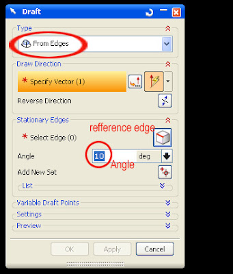
taper angle is one basic editing feature that must have to know, why because like designer CAD in mold, die casting, and various CAD design machine always using some taper in their product of course with their various each reason to do that.so.. let's begin learning more about make some taper.there are 4 concept to make taper in Unigraphics NX5 by using edges, from plane, tangent to face and to parting edge.now we begin from number one using edgesto begin taper operation click draft icon in Unigraphics NX5 like picture belowafter that taper dialogue box will appear, like picture belowmake sure you choose from edges and fill the angel do you want,...

Wednesday, 3 September 2008

Move Point to Point then subtract

although subtract command was post in some month ago, i think is important to make subtract tutorial again, becouse it related to some post that i will made.Move Point to Pointis the simple and the fast way to move object using point. the step just0. click transform or CTRL + T, click translate to point1. Select the object2. select point constructor (end point, middle point, center and so on)3. select the point at the object4. select the point where the object want to move.5. select move or copy then OK or Cancel.Online Videos by Veoh.comSubtract.the step to make subtract are0. Click subtract icon1. select the body target2. select the body tool3. OK it easy right, save your object, becouse we will use in other post...

Monday, 1 September 2008

setting Unigraphic Environment, Display and Object

the video tutorial below explain setting the environment display, object and background, some setting is to improve speed of rendering graphics, to speed up rendering graphics 1. change the background environment with plain color2. minimum the light (off setting for two side light)3. disable translucency 4. change the line with thin line.5. use wire view is more faster then shaded viewfrom picture above we can edit visualization by clicking preferences then Visualization and we can also change the performance of rendering by setting some parameter in Visualization Performance, One step below the visualization Online Videos by Veoh.combetween...

 
Design by Free WordPress Themes | - Premium Blogger Themes |