Get Unigraphics Tutorial from begining untul advance here
Please share this blog on your social network, it's make this blog keep a live and have more post,
leave some comment if you need further help

Monday, 23 March 2009

record, call, and using macro in Unigraphics

Macro is important to make fast design, because we can cut step design that too long became more shorter, we also can make hot key that run macro, so some command that must repeated to doing something can be make more shorter.

at this post we will learn about
How to Start Macro
How to records Macro
step by step to make Macro
adding Macro to your own command

read more below
Begin Macro in Unigraphics

you can also download the tutorial at link below
Macro of Unigraphics NX


Sunday, 15 March 2009

Make Your Own toolbar in Unigraphics NX

one advantage using unigrpahics is easy toolbar customization, so we can make own toolbar, set various icon, macro and history macro, it make unigraphics more user friendly.

about 3 month i did't write any unigraphics tutorial again, i hope from this post i can more get free time to write tutorial. to make advance Unigraphics toolbar that consits of macro, history macro, etc always need basic knowledge to make toolbar, tutorial below give some simple way to make toolbar and entering some command on it.

because i have very very limited bandwidth internet, i make this tutorial not directly write in this post, i use word processor then post it in scribd.com and embed it in this post, so you can read it directly, i also provide download link to download it, i uploaded it ziddu.com because box.net seem to be some error ( sorry i using ziddu)

download it in this link
http://www.ziddu.com/download/3877182/yourowntoolbar.pdf.html

or read it here directly


Make Your Own Toolbar in Unigraphics NX

Tuesday, 3 March 2009

Understanding centrifugal pressure load simulation in Unigraphics

A Centrifugal Pressure Load enables you to create and analyze radial varying centrifugal pressure loads. This feature is similar in functionality to the existing hydrostatic pressure loading capability. Centrifugal pressure loads exist whenever there is a liquid spinning in an object where the liquid is moving away from the axis of rotation. Examples of radial varying centrifugal pressure loads include, but are not limited to:
•Rotating pistons
•Rotating drums, such as centrifuges, wash machines, and dental centrifugal casting machines
•Rotating turbines, such as those found in hydroelectric power plants

centrifugal pressure load calculated using:
• Liquid density
• Static pressure
• The angular velocity of a spinning vessel
• The radial offset from the location where a liquid is injected (if not directly on center)

because limitation if internet connection, i can't upload picture again in blogger, so i try to upload document in scribd.com so for more information about centrifugal pressure load please read below documentation


Advance Simulation

Friday, 14 November 2008

reblend face using direct modeling feature

direct modeling that provide by Unigraphics is very help full, specially when the part parameter was removed, so we can edit it directly by clicking the parameter, but using direct modeling feature we can edit it directly.

face that was blend by certain radius value also can edit by using reblend face feature in direct modeling, to begin those feature
1. click reblend face, rebled face dialog box will appear
2. select blend part of the product or part
3. change the value
4. click Apply or OK


see picture below


i also publish video using veoh.com
see tutorial video below

Watch reblend face in How to Videos  |  View More Free Videos Online at Veoh.com

Make same face using replace face feature

this is one from various feature of direct modeling, this command available from Unigraphics NX1 until Unigraphics NX6, the function of this command is make same flat or same position of face that have different hight,
in the direct modeling feature, Unigraphics give us to editing face and solid model directly like change diameter of cylinder, or arch face, change radius of blend directly and others although the part parameter is removed.

to begin direct replace face command click the picture like below


after dialog box appear select the face that you want to move, select third button then select the target face, click OK or Apply
to make tutorial more easy to understand i post video, hope this useful

Watch direct modeling replace face in How to Videos  |  View More Free Videos Online at Veoh.com

other tutorial also available in the post
http://ugs-tutor.blogspot.com/2008/08/making-block-from-block-offset-ediitng.html

Saturday, 18 October 2008

multiple copy part using transfrom in Unigraphics

when works with part that have a pattern or same shape, using multiple copy is very helpful, although various way to create multiple part available in Unigraphics, at this tutorial focused using transform and multiple copy button only.
to begin transform operation click transform button or using short cut CTRL+T, the transform dialog box will appear like picture below


the target from this tutorial is make multiple part from single part, like picture below


those pattern part made from one block, which choose button when using transform, those pattern can be made more fast.

Watch copy multiple part in How to Videos  |  View More Free Videos Online at Veoh.com

Step to make those pattern part are
1. make the block with dimension
X = 100
Y = 100
Z = 50

2. change the color by using CTR + J
3. click transform icon (CTRL + T)
4. select the part,OK
5. select and click Tranfrom Button
6. select delta
X = 50
Y = 50
Z = 0
7. Click OK
8. select multiple copy Avail
at the number of copies column fill the 5 or any number what you like, select OK,
Select Cancel to end the operation
9. Right Click and select FIT to fit with your screen.

at those video, the part before multiple operation selected, i try to copy, and move,i hope it's more help to understand the different between copy, move and multiple copy, you can also Undo the operation by click Undo the last Operation

Wednesday, 8 October 2008

Starting Drafting a model in Unigraphics

after we make some model, or part, we need draft the model, drafting is not just give the measure of size of model, but we can put tolerance, setting width of line in drafting and plot it.
oke, let's start drafting in unigraphics NX
to start drafting, from start klik drafting, like picture below
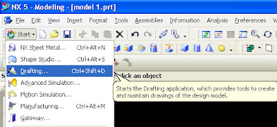


after click drafting, the window will change to drafting window, like picture below
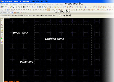
(please click it to enlarge, the fact in picture above have grid view and clear toolbar icon)

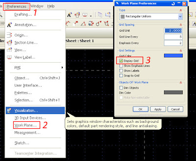
first time the drafting environment start, it always have grid in the screen, we can remove it by clicking
1. preferences
2. Work Plane
3. after Work Plane window appear, uncheck grid check box, like picture below


when starting drafting, we always get some question about new sheet parameter in sheet window like picture below
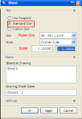
set standard size, then select paper size that you want use in drafting, it's from A0 until A4, after select paper size, select scale of part 1:1 it mean drafting and real model will same. then click OK.


video below will explain more clear step by step to begin drafting


Watch start drafting in How to Videos  |  View More Free Videos Online at Veoh.com

Base View
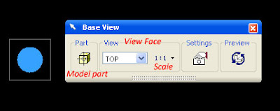
Base view is first view that will become base, from this view we will make other projected view, we can select various kind of base view, not always from top, for example right view, left view or bottom view can also become base view. at the base view window we can also select scale, and part or model if we have more than one model or part in modeling worksplane. picture below is little explanation of base view
 
Design by Free WordPress Themes | - Premium Blogger Themes |