Get Unigraphics Tutorial from begining untul advance here
Please share this blog on your social network, it's make this blog keep a live and have more post,
leave some comment if you need further help
Showing posts with label intermediate. Show all posts

Saturday, 20 November 2010

Make helix and cube, spring shape a like in Unigraphics Siemens PLM software

Icon helix serves to make the basic form helix formation, this formation can be developed into a screw, spring, hose and other formations that have similar shape, to begin click insert -> helix

Helix Dialog Box
on the helix dialog box, choose number of turn and pitch, number of turn-helix is the number of rounds that will be constrained, while the pitch is the distance per one rotation between helix one with the other.
for example put 3 on the number of turn and the pitch 100 mm, and radius 200 mm, click on the screen of unigraphics or select point constructor to select datum for make helix.
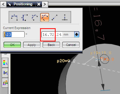
In the default direction of helix always Z, to change those direction click Define Orientation button


make helic and tube

Friday, 13 August 2010

extract curve and project curve

Curve operation in Unigraphics NX5 is very interesting,because it easy to operate as our need,
EXTRACT CURVE
first let's learn about extract curve, From the edge of the face may sometimes be necessary to draw a line, if the face is a connection between two or more face we do not need to draw it, use the extract face an easier way.in the figure below, we need a line that curved to explain about partings line (mold design).
 The first step is to click the icon extract the curve, the shape iconya like the image below, if the icon is missing, to appear in the toolbar curve and curve editing.


after clicking the icon extract the curve there is a dialog box option to extract the curve, such as the following picture


there are various options for extracting the curve,1. curve for extracting edges from the edge curve, Every face, body That edge cans containing changed from a line.2. isoparametric curve, for extracting isoparametric curve.3. silhouette curve, extract the curve from the views which we look directly at the monitor.4. All in work view5. isocline curve6. shadow outline
in this example choose the number one edge curve, and then click the edge you want in the extract, the result like the picture beriku, you'll get a line in accordance with the selected edge shapes, although the formation of the arch, loop, etc.


PROJECT CURVE
while the "project curve" is used to make a line on the project area, this is used when we created a line that can not directly be made on a face, for example due to the curved face, simply by making a line with the project above the curve we can draw a line in accordance with arch shape.


There are three steps for the project curve 
1. select the line that will be projected
 2. then click face for project area
3. click OK, then you have line on that face.


Monday, 23 March 2009

record, call, and using macro in Unigraphics

Macro is important to make fast design, because we can cut step design that too long became more shorter, we also can make hot key that run macro, so some command that must repeated to doing something can be make more shorter.

at this post we will learn about
How to Start Macro
How to records Macro
step by step to make Macro
adding Macro to your own command

read more below
Begin Macro in Unigraphics

you can also download the tutorial at link below
Macro of Unigraphics NX


Sunday, 15 March 2009

Make Your Own toolbar in Unigraphics NX

one advantage using unigrpahics is easy toolbar customization, so we can make own toolbar, set various icon, macro and history macro, it make unigraphics more user friendly.

about 3 month i did't write any unigraphics tutorial again, i hope from this post i can more get free time to write tutorial. to make advance Unigraphics toolbar that consits of macro, history macro, etc always need basic knowledge to make toolbar, tutorial below give some simple way to make toolbar and entering some command on it.

because i have very very limited bandwidth internet, i make this tutorial not directly write in this post, i use word processor then post it in scribd.com and embed it in this post, so you can read it directly, i also provide download link to download it, i uploaded it ziddu.com because box.net seem to be some error ( sorry i using ziddu)

download it in this link
http://www.ziddu.com/download/3877182/yourowntoolbar.pdf.html

or read it here directly


Make Your Own Toolbar in Unigraphics NX

Friday, 14 November 2008

reblend face using direct modeling feature

direct modeling that provide by Unigraphics is very help full, specially when the part parameter was removed, so we can edit it directly by clicking the parameter, but using direct modeling feature we can edit it directly.

face that was blend by certain radius value also can edit by using reblend face feature in direct modeling, to begin those feature
1. click reblend face, rebled face dialog box will appear
2. select blend part of the product or part
3. change the value
4. click Apply or OK


see picture below


i also publish video using veoh.com
see tutorial video below

Watch reblend face in How to Videos  |  View More Free Videos Online at Veoh.com

Make same face using replace face feature

this is one from various feature of direct modeling, this command available from Unigraphics NX1 until Unigraphics NX6, the function of this command is make same flat or same position of face that have different hight,
in the direct modeling feature, Unigraphics give us to editing face and solid model directly like change diameter of cylinder, or arch face, change radius of blend directly and others although the part parameter is removed.

to begin direct replace face command click the picture like below


after dialog box appear select the face that you want to move, select third button then select the target face, click OK or Apply
to make tutorial more easy to understand i post video, hope this useful

Watch direct modeling replace face in How to Videos  |  View More Free Videos Online at Veoh.com

other tutorial also available in the post
http://ugs-tutor.blogspot.com/2008/08/making-block-from-block-offset-ediitng.html

Saturday, 18 October 2008

multiple copy part using transfrom in Unigraphics

when works with part that have a pattern or same shape, using multiple copy is very helpful, although various way to create multiple part available in Unigraphics, at this tutorial focused using transform and multiple copy button only.
to begin transform operation click transform button or using short cut CTRL+T, the transform dialog box will appear like picture below


the target from this tutorial is make multiple part from single part, like picture below


those pattern part made from one block, which choose button when using transform, those pattern can be made more fast.

Watch copy multiple part in How to Videos  |  View More Free Videos Online at Veoh.com

Step to make those pattern part are
1. make the block with dimension
X = 100
Y = 100
Z = 50

2. change the color by using CTR + J
3. click transform icon (CTRL + T)
4. select the part,OK
5. select and click Tranfrom Button
6. select delta
X = 50
Y = 50
Z = 0
7. Click OK
8. select multiple copy Avail
at the number of copies column fill the 5 or any number what you like, select OK,
Select Cancel to end the operation
9. Right Click and select FIT to fit with your screen.

at those video, the part before multiple operation selected, i try to copy, and move,i hope it's more help to understand the different between copy, move and multiple copy, you can also Undo the operation by click Undo the last Operation

 
Design by Free WordPress Themes | - Premium Blogger Themes |