Get Unigraphics Tutorial from begining untul advance here
Please share this blog on your social network, it's make this blog keep a live and have more post,
leave some comment if you need further help

Friday 14 November 2008

reblend face using direct modeling feature

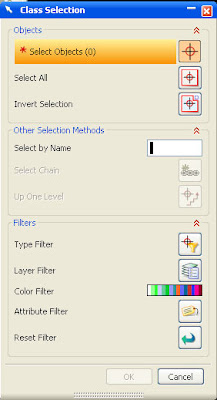
direct modeling that provide by Unigraphics is very help full, specially when the part parameter was removed, so we can edit it directly by clicking the parameter, but using direct modeling feature we can edit it directly.

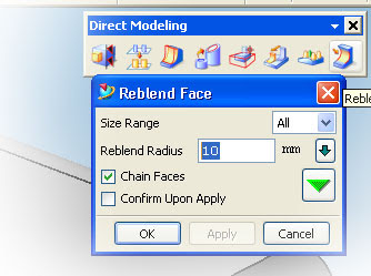
face that was blend by certain radius value also can edit by using reblend face feature in direct modeling, to begin those feature
1. click reblend face, rebled face dialog box will appear
2. select blend part of the product or part
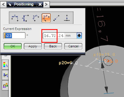
3. change the value
4. click Apply or OK


see picture below


i also publish video using veoh.com
see tutorial video below

Watch reblend face in How to Videos  |  View More Free Videos Online at Veoh.com

Make same face using replace face feature

this is one from various feature of direct modeling, this command available from Unigraphics NX1 until Unigraphics NX6, the function of this command is make same flat or same position of face that have different hight,
in the direct modeling feature, Unigraphics give us to editing face and solid model directly like change diameter of cylinder, or arch face, change radius of blend directly and others although the part parameter is removed.

to begin direct replace face command click the picture like below


after dialog box appear select the face that you want to move, select third button then select the target face, click OK or Apply
to make tutorial more easy to understand i post video, hope this useful

Watch direct modeling replace face in How to Videos  |  View More Free Videos Online at Veoh.com

other tutorial also available in the post
http://ugs-tutor.blogspot.com/2008/08/making-block-from-block-offset-ediitng.html

Saturday 18 October 2008

multiple copy part using transfrom in Unigraphics

when works with part that have a pattern or same shape, using multiple copy is very helpful, although various way to create multiple part available in Unigraphics, at this tutorial focused using transform and multiple copy button only.
to begin transform operation click transform button or using short cut CTRL+T, the transform dialog box will appear like picture below


the target from this tutorial is make multiple part from single part, like picture below


those pattern part made from one block, which choose button when using transform, those pattern can be made more fast.

Watch copy multiple part in How to Videos  |  View More Free Videos Online at Veoh.com

Step to make those pattern part are
1. make the block with dimension
X = 100
Y = 100
Z = 50

2. change the color by using CTR + J
3. click transform icon (CTRL + T)
4. select the part,OK
5. select and click Tranfrom Button
6. select delta
X = 50
Y = 50
Z = 0
7. Click OK
8. select multiple copy Avail
at the number of copies column fill the 5 or any number what you like, select OK,
Select Cancel to end the operation
9. Right Click and select FIT to fit with your screen.

at those video, the part before multiple operation selected, i try to copy, and move,i hope it's more help to understand the different between copy, move and multiple copy, you can also Undo the operation by click Undo the last Operation

Wednesday 8 October 2008

Starting Drafting a model in Unigraphics

after we make some model, or part, we need draft the model, drafting is not just give the measure of size of model, but we can put tolerance, setting width of line in drafting and plot it.
oke, let's start drafting in unigraphics NX
to start drafting, from start klik drafting, like picture below


after click drafting, the window will change to drafting window, like picture below

(please click it to enlarge, the fact in picture above have grid view and clear toolbar icon)

first time the drafting environment start, it always have grid in the screen, we can remove it by clicking
1. preferences
2. Work Plane
3. after Work Plane window appear, uncheck grid check box, like picture below


when starting drafting, we always get some question about new sheet parameter in sheet window like picture below

set standard size, then select paper size that you want use in drafting, it's from A0 until A4, after select paper size, select scale of part 1:1 it mean drafting and real model will same. then click OK.


video below will explain more clear step by step to begin drafting


Watch start drafting in How to Videos  |  View More Free Videos Online at Veoh.com

Base View
Base view is first view that will become base, from this view we will make other projected view, we can select various kind of base view, not always from top, for example right view, left view or bottom view can also become base view. at the base view window we can also select scale, and part or model if we have more than one model or part in modeling worksplane. picture below is little explanation of base view

Sunday 28 September 2008

setting environment of Unigraphics NX 5, background and line width

default setting in UGS NX 5 and previous UGS the line thickness of part is always width, this view is doesn't good when we design a lot of part, because it'll difficult to find touching line between face and face.
so some designer product that using UGS always like the thickness or line part is thin, because it more comfortable in our eyes.
to change the width of line product step are
1. goto preferences
2. visualization
3. go to tab line
4. remove check on the width check box
5. click apply
6. click cancel

video below is step by step tutorial to change the thickness line of part.


Online Videos by Veoh.com

beside change the the thickness line of part, at video above we can also learn how to setting your background, setting the NX5 Environment. it same with setting the thickness, but click color tab to edit the background color.

set the background with your favorite color

Saturday 27 September 2008

making cone with cylinder base

Now let's turn with beginner level again, simple way to make cone with subtract at the end with cylinder, now to make easier learning from this blog, i post include the dimension of the part that we'll make it.

the dimension is very simple, cylinder with cone, to drawing it in Unigraphics actually is divide in 2 part, cylinder and cone, you can make cone first then cylinder or cylinder first than cone, because the datum of X,Y,Z is located in cylinder, i prefer begin it from cylinder, because it more easy.

Ok, see the the dimension below


first time make the cylinder with height 30 and diameter 10
than make cone with base cylinder, height 15, base diameter 10 and half angle 10

to learn more see video below

Tuesday 23 September 2008

making simple pastic part, hole and shell from 2D data

although that in previous post we has learn how to make simple shell, below i try to post some more interesting using shell and hole to make simple plastic part.

oke below is the drafting, include 2D CAD data, hope from those 2D let's try to make become 3D data


just click the image to enlarge
from those 2D data after we make become 3D data is like picture below


then how to make those step by step using fast and simple way in Unigraphics? video below is the answer, after watching video below, try it by your self.
the simple step to make those part are
1. make the outline , Box 50 x 50 x 50
2. make the hole, diameter 30 and from the posisition is center (25 from each side)
3. make the thickness using shell, with value 2


Online Videos by Veoh.com

Wednesday 17 September 2008

Shell Process, make thickness all of part same

with shell process we can make thickness all of part same with one click, this icon is very useful for plastic part designer, and others engineer that work with thickness of product.

step to begin shell process are
1. click the icon
2. select the datum of part, the datum commonly are face or part, be careful selecting the datum becouse it influence the result and direct of shell process
3. set the thickness.
4. click OK, Apply or Cancel.

see more step by step shell the product and removing face at video below


Online Videos by Veoh.com

after shell process you will also learn, cutting view in video above, with cutting view we can see directly hole, removed face, and other section.

Friday 5 September 2008

draft angle, taper angle from edges and blend

taper angle is one basic editing feature that must have to know, why because like designer CAD in mold, die casting, and various CAD design machine always using some taper in their product of course with their various each reason to do that.

so.. let's begin learning more about make some taper.
there are 4 concept to make taper in Unigraphics NX5 by using edges, from plane, tangent to face and to parting edge.
now we begin from number one using edges

to begin taper operation click draft icon in Unigraphics NX5 like picture below


after that taper dialogue box will appear, like picture below


make sure you choose from edges and fill the angel do you want, from this step
1. click the face as the datum reference.
2. click the edge that become stationary point.
3. click Apply button or OK

see the picture below to learn each step


i also provide fast and easy video tutorial, see more at embed object below, you need to install flash palyer9 to see embed object below.
at this video you also can learn how to bled the edges of object


Online Videos by Veoh.com

Wednesday 3 September 2008

Move Point to Point then subtract

although subtract command was post in some month ago, i think is important to make subtract tutorial again, becouse it related to some post that i will made.

Move Point to Point

is the simple and the fast way to move object using point. the step just
0. click transform or CTRL + T, click translate to point
1. Select the object
2. select point constructor (end point, middle point, center and so on)
3. select the point at the object
4. select the point where the object want to move.
5. select move or copy then OK or Cancel.


Online Videos by Veoh.com

Subtract.
the step to make subtract are
0. Click subtract icon
1. select the body target
2. select the body tool
3. OK

it easy right, save your object, becouse we will use in other posting

Monday 1 September 2008

setting Unigraphic Environment, Display and Object

the video tutorial below explain setting the environment display, object and background, some setting is to improve speed of rendering graphics,
to speed up rendering graphics
1. change the background environment with plain color
2. minimum the light (off setting for two side light)
3. disable translucency
4. change the line with thin line.
5. use wire view is more faster then shaded view


from picture above we can edit visualization by clicking preferences then Visualization and we can also change the performance of rendering by setting some parameter in Visualization Performance, One step below the visualization


Online Videos by Veoh.com


between that you can change the background color, width oh the line object and so on
learn more by view video above

Sunday 31 August 2008

layer setting operation, statics wire frame view mode

tutorial below is simple way to view your object in wire frame, so we can choose some view mode in unigraphics like solid body, sheet body,statics wire frame, shaded view and others

Online Videos by Veoh.com

then after learning view mode, we can learn how to manage object using layer setting. at the sample video above is mold construction 3D model plate with basic bolts, then i want to hidden the bolts in other layer, so we need to manage an object in different layer. basically default setting working layer is always layer 1.

step to move object in different layer are
1. click the move to layer setting icon.
2. click the object that want to move to others layer
3. layer dialog window will appear select the layer number or just type the number that you want.
4. select OK

maximum layer number in unigraphics is 256
look at video above to learn more

With NX5, you can control whether objects are visible or selectable by using layers. A layer is a system-defined attribute that all objects in NX5 must have, such as color, font, and width. by organizing object in layer it will make rendering object more faster, and easy to manage for example when work with large and huge model,all bolts is in one layer, pipe in other layer and so on. There are 256 usable layers in NX5, one of which is always the Work Layer. Any of the 256 layers can be assigned to one of four classifications of status:
• Work
• Selectable
• Visible Only
• Invisible
The Work Layer is the layer that objects are created ON, as i told before when we not set the working layer, we always work in default layer number 1.and is always visible and selectable while it remains the Work Layer. When the Work Layer is changed to another layer, the previous Work Layer automatically becomes Selectable and can then be assigned a status of Visible Only or Invisible.
The number of objects that can be on one layer is not limited but more object in one layer it's make loading and rendering object more slow, so manage using layer is important when we working with large, detail and a lot of object. You have the freedom to choose whichever layer you want to create the object on and the status of that layer.

Saturday 16 August 2008

Split a block, Using Split Body Command

In Unigraphics from NX1 until NX5, Split Body command always available, this command is easy to use, easy to split a block, body or part that we make before, there are various parameters that we can use to split body, for example using circle, plane, face, two line, two line with length on circle, UCS and Axis and others.

embed video below is shown step to step split a block become two block, i post the video in veoh, some times it's need long time to load this video, just be patient

Online Videos by Veoh.com


use icon like picture below to begin split body command.

Be careful

why becouse split body command will remove all parameters from body or part after we split, so we can not edit those body again using editing parameters.

use point and distance then click the plane

Saturday 9 August 2008

making Block from Block, offset ediitng , Replace face

video tutorial below i make special for beginner, make block from block before or the datum reference is previous block, it's will help to design some part that use block or plate often, like mold / mould base, casting mold, injection mold and other's.

the basic step is like tutorial before, see at http://ugs-tutor.blogspot.com/2008/06/basic-block-using-two-point-and-height.html
yes.. it's basically same, the different is point that we must selected, then the editing after we make the block.

see the video below

Online Videos by Veoh.com

Editing Process
below some editing that i use in those video

Replace Face
use this icon to activated replace face.


after you click those icon, the dialog box will appear, first selection, select the face that you want edit, second button selection is for reference face that you wanted. first face will same with the second face position.
it's fast way to edit face than we fill some value.


Offset Editing
to learn step by step to offset editing you can look at previous post
http://ugs-tutor.blogspot.com/search/label/offset


use the icon like picture below to activated offset operation

Tuesday 5 August 2008

Transparent the object,offset same region, move together in Unigraphics (UGS NX)

at this post below we can learn how to make objects become transparent so we can look the inside of those object, than how to move together a face using offset region.

Transparent an Object
it's cool and sometimes important to make an object become transparent, becouse sometimes we need to look the object in inside the other object more detail.
picture below shown an object with transparent view.


at those sample picture we can see the inside of same object using transparent.
tho make object transparent, you can click object display icon, or by short cut CTLR+J, after that the class selection window will appear


click the object or part, then click OK, or press center button of your mouse. then change the translucency value more than 0,


then click APPLY or OK
or see the complete video tutorial below

Online Videos by Veoh.com

at those video you can also learn how to move face together more than one object or parts. it's simple, just use offset icon then select together the face that want to move, enter the value then click OK.

Friday 25 July 2008

Split part using curve, delete unwanted part

after for a while i did't update this blog, now let's learn simply way to cut or split part using curve, then delete unwanted part and unite some part.

Split Body Icon
by using this icon, we can divide body part using two line, plane, parallel plane, curve and diameter of cylinder.

i was captured my screen using free software"auto screen recorder 3" this software is easy to operate and free, although there is no editing tool at those software.

below is video that i upload in veoh, by looking this video you can also see step by step to split part, delete unwanted part and unite other part.


Online Videos by Veoh.com

step by step to split an part :
1. select split body icon.
2. select the part.
3. define the plane (choose cylinder).
4. choose arc / circle.
5. select the arc of cylinder.
6. click ok.
7. select other object to repeat the operation or cancel to finish split operation.

try using other part and cylinder or hole.

Saturday 12 July 2008

Rotate and Copy Object in Unigraphics

Video below is other operation of transformation in Unigraphics, if previous post we have learned to rotate some object or part, now at this video we will learn to rotate and copy the object.

to begin transform operation is same with previous post, use short cut CTRL + T, after class selection window appear select the object and so on, at the end, when move and copy button appear select copy.

look the video below to learn more

Online Videos by Veoh.com

Friday 11 July 2008

Rotate an object by point and two axis in Unigraphics

some times we need to rotate our object or part that we draw in UGS, they are some way to rotate an object in UGS, video below will shown how to rotate using point and two axes,

the basic principle is, point that we select will become point reference (0,0,0) than two axes selected become direction, at this video sample Y and Z, axis that does not selected will become rotation axis (at this example X axis)


Online Videos by Veoh.com

step to rotate using two axis
0. begin operate with transforms click CTRL + T in your keybord
1. select object , then click OK
2. select rotate by two axes.
3. select the point.
4. select first axis, then click OK
5. select second axis, click ok
7. fill the angle that you want rotate.
8. click copy or move.

Thursday 10 July 2008

Transform and Moving Part Operation, point to point

now let's learn basic transform operation, to begin transform click using shortcut CTRL + T, together, class selection object dialog box will appear like picture below


for example i have two object, and i want to transform the green pipe to outer side, after class selection object appear, click the green pipe that we want to move


green pipe color will change after selected, now transformation dialog box will appear like picture below


at those dialog box, choose transform , we can choose point to point or using delta length of movement, choose point to point


make sure your quadrant point icon is on position and center circle in off position


then select quadrant in drop down menu like picture below


click quadrant position at green pipe,click MB2 (center/scroll mouse), then click target the other quadrant object.
then click move to move without copy, or select copy if want copy those object to others position.

Friday 27 June 2008

Basic block using two point and height specified

Basic tutorial to make 3D block using two point and height specified, step to make block are
1. click icon block


2. select two point and height,number two icon like picture below


3. Top view your screen
4. select two point at your screen
5. click OK

video tutorial also available below


Online Videos by Veoh.com

Thursday 26 June 2008

Make Array hole in cylinder, Circular pattern, Unigraphics Tutorial


make array face in cylinder like hole, boss or other shape is easy using Unigraphics, to begin make array model, use pattern face, this icon located in direct modeling tool bar, by using this icon we can make array face, circular pattern face, rectangular array face in other.
click the icon of pattern face like picture below


if you prefer learn using video, here i capture step to make array pattern

Online Videos by Veoh.com direct

Step by Step to make circular array
1. make a cylinder with diameter 50 and height 10, you can use icon cylinder in feature toolbar, or look how to make cylinder at this post http://ugs-tutor.blogspot.com/2008/06/make-simple-bolt.html


then at the dialog box fill diameter with 50, and height 10 like picture below

2. at the cylinder make hole with diameter 5, click the icon hole at feature toolbar.

at the hole dialog box, fill the value and make sure your hole type (plain hole type- little red box at this picture)select face of cylinder using MB1 (left click)

select positioning method or accept default value (it always at number 3 button from right)then click OK, or if you prefer make hole with certain value from center cylinder, choose number 4 button from right, look at picture below


then select the edge of your cylinder


select end point button, dialog box like below will appear


fill those box with 15, then click OK, now you have cylinder with one hole

3. Make circular array
click the icon like picture below
after click the icon the dialog box will appear, choose circular pattern like picture below,


fill the number and angle like picture above. then click the face of hole in the cylinder, click MB2 (center mouse button) twice until inferred vector button on, then select Z axis arrow, finished with OK button.

or see the easy tutorial via video, your browser must installed latest adobe flash player.

Thursday 19 June 2008

Make Shaft using Sketch and Revolve

by using revolve we can make simple and complex 3D model from 2D model that have cylinder shape, like shaft, bolt, drum, pulley, fly wheel and other cylinder product.
now our project at this post is make shaft like picture below


Step to make shaft are
1. open sketch
2. make a half 2D shaft using profile
3. finish sketch , revolve the half 2D sketch model.

to begin using revolve, click in the feature toolbar, like picture below


to learn step by step of this tutorial, please refer to video below to learn make shaft using revolve feature, here i try to upload in veoh, because i think veoh video quality is better than youtube, although same times any advertisement added in video


Online Videos by Veoh.com

Wednesday 18 June 2008

Begining Sketch Operation, Extrude

last month i post how to make block easier using Form Feature Operation, now let's learn make more attractive block using sketch in unigraphics NX5, sketch is basic feature in UGS that we can make block, cylinder, pipe and other 3D model from 2D model. so let's try make 3D model from 2D model.
Begin Sketch using Icon
to begin sketch click the sketch icon like picture below, it usually located at feature tool bar.


to see how to use sketch, to make block, try to play this video


after clicking the icon, next step is define the plane of sketch, default plane are X -Y plane, if we clicking OK to the default value, we will make sketch plane on X - Y Plane. as see on picture below, we can choose sketch plane. direction of plane, plane option and reference. at this tutorial we use X-Y default plane.


after click OK, Sketch plane will available, at those plane we can drawing using 2D model type like line, arc, profile, circle. try using profile to make like continues line connection.

we can choose preferred snap point option, when we choose profile we also can choose basic shape, line or arc.

begin to sketch with 0,0 coordinate, click the 0,0 then bring it horizontal click other position and the closed line connection like picture below.


then after make closed connection line, right click your mouse choose OK.


EXTRUDE OPERATION

we can make 3D model using extrude operation from 2D model like sketch or line, to begin extrude operation click the extrude icon


dialog box will appear, fill the end distance value 25, then click to 2D sketch line, click OK.


3D model from extrude and sketch will appear like picture below

 
Design by Free WordPress Themes | - Premium Blogger Themes |