Get Unigraphics Tutorial from begining untul advance here
Please share this blog on your social network, it's make this blog keep a live and have more post,
leave some comment if you need further help

Tuesday 20 December 2011

Syncronous Modeling : Replace Face, make the same high surface

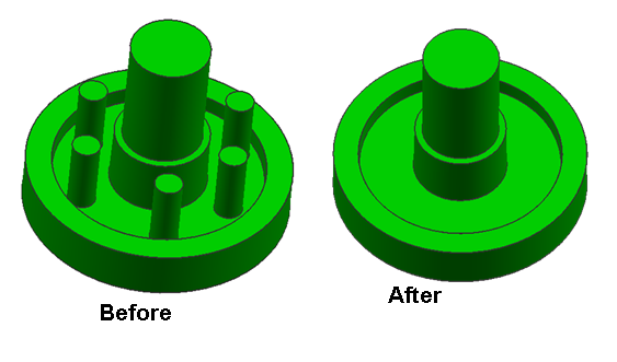
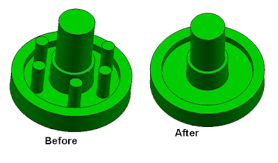
replace face is very useful to change the shape so as to have the same height, so that a variety of complex shapes can be changed quickly using this feature.
By replace face, we can move or make the face height same with another face
Step 1. Click Icon Replace Face

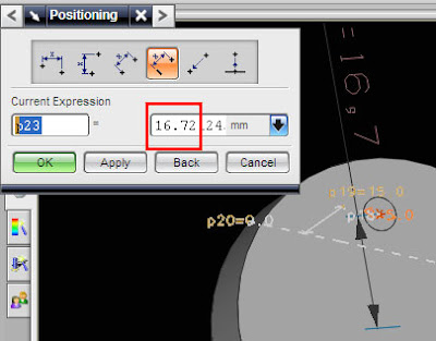
Step 2. Dialog Box will appear, select the face that you want to change the height. make sure the Select face on Face to Replace become green checked.

step 3. select destination face or replacement face. make sure the replacement face become green checked. then click OK or Apply, by default  offset distance is zero.


Syncronous Modeling : Using Offset Face

By this order not only face with straight shape, but this command also can use for diameter, radius, etc

when the form object in the offset is the radius or chamfer, and the offset direction leads to one side, then the radius or chamfer can be delete automatically.
Step : click the icon, select the face, and enter the value, or drag the green arrow, then click OK or Apply


Syncronous Modeling : Using Pull Face

Basic function is same with move face, we can use this icon to move the face together like on move face
when we pulled to the outside, it automatically adds appropriate material with a face that we draw, if we draw inward, Object automatically will subtract with the face shape that we draw.


Step : select the icon, select the face (you can select more than 1 face), select motion type, defaulth is distance, then enter the distance value or drag the green arrow.


click Apply or OK to finishing the pull face.

Syncronous Modeling : Using Move Face, Edit Object after remove parameter

Unigraphics is one of the ease of convenience in editing objects even after they are done remove the parameters, syncronous Modeling feature, it helps us to edit the objects that had no parameters. to issue a syncronous Modeling toolbar, can be done by right clicking on an empty toolbar and check the syncronous modeling, or it could be the Insert Menu - choose syncronous Modeling.
before you remove the object parameters, the shape of an object can be changed easily through the parameters, for example by double-clicking the object, then the parameters that can be edited will be displayed


After applying remove parameter, we still can edit the value of aur design using syncrhonous modeling feature, one of them is move face.
In NX 6 we can move face directly by click and drag, and we can use in more than 1 face together
Step : Select move face icon,  select motion type, then select face, enter the value or drag the green arrow by mouse

Click Move face Icon

dialog box of move face will appear like picture below

select transform motion, Distance to move straightly, or select angle if you want move to certain angle.


select face, we can select more than one face, enter the value, or drag the green arrow. click OK or Apply.

export and import file in Unigraphics NX 6

basically it's still same with other version, to export and import files, you can use the menu file-import-then choose the file type, there are several types of files that can be used to communicate with other CAD software.

export and import files are very useful for communicating with other CAD software, UG can communicate easily with many types of files, ranging from the STP, IGES, both 3D and 2D DWG, DXF, Parasolid, etc.
Unigraphics NX 6 has a convenience, files created with Unigraphics, sometimes to be opened in Solid Works, without having to mengkonvertnya first, but the Solid Works file (sldprt) could not be opened directly, must convert it first.


in deflaut, when a file of solid work we export as stp, the file will have the extension. STEP, this extension can not be imported directly by Unigraphics, Step file types that can be imported by Unigraphics are ending. stp, so you have to change their file extension of. STEP rename it (select and click F2) Become. stp, after renaming the extension, using import stp file import and select the file format.

Monday 12 December 2011

Extrude from face, edge, line and sketch in Unigraphics NX 6

to start the extrude in NX 6 there are many options, you can use the extrude command from the sketch, line, edge, and face, various extrude option makes it easy for you to make part

Extrude from Sketch
Click Insert -> Sketch

Select Plane, XY, YZ or XZ, or you can choose face from objects that already exist
Draw your sketch, begin your sketch from line, or polyline, circle,etc. after your sketch was completed, finish your sketch (see picture below)


 then click icon extrude then on filter option select connected curves,


then : select your curve, then enter the Z value, click OK to finish it,

Extrude from Line
Make your line, or from exiting line, click extrude icon, on filter selection. Select single curves, then select your line

 on the dialog box like below, setting  your limit value, and offset setting, click OK, if finished

Extrude Face
Click extrude icon,on curve rule select face edge, then select the face of your part, Drag the arrow or enter the extrude value, clik OK to finished

Friday 25 November 2011

activate full view in Unigraphics NX 6

started on UGS NX 6 upwards there a special button to switch the display, from the display as usual (there is a toolbar, menu, selection, in addition to above, right, left and bottom sometimes) to display full view, the position of the toolbar move downward with ribbon system , classified by type of toolbar, these views simplify the design, but it takes practice to get used.
picture below is the view you normally see from Unigraphics NX1 up to Unigraphics  NX 5

 while the image below is a full picture view to NX 6 with toolbars and menus are grouped in a ribbon at the bottom


to change the look of a full view into plain view, and otherwise, you can use the buttons on the right above, (i red circle), a small button that will make you more comfortable to do presentations that require the display width

Thursday 11 August 2011

Change shaded edge color

Same with previous post, click Visualization -> Preferences
On visualization Preferences dialog box
Look at shaded edge color, click specify color,


then select color on the right color box, for the example I choose red color for the edge


Click OK after finishing 


Monday 1 August 2011

Replacing thick of edge in Unigraphics

the need for thick lines display each time a different design, when designing a part with small amounts, but complicated, and it takes a good picture view, a rather thick line help make it easier to see edge of an object, picture below is the object with a thin line


to change the thickness, on the main menu above click preferences and select Visualization,


The next step is to check the check box on Show Width, then click OK, done, your visualization of part in Unigraphics will change, picture below is a comparison of differences in thickness

dialog box as below will appear


picture below is a comparison of differences in thickness

 
Design by Free WordPress Themes | - Premium Blogger Themes |