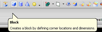
make array face in cylinder like hole, boss or other shape is easy using Unigraphics, to begin make array model, use pattern face, this icon located in direct modeling tool bar, by using this icon we can make array face, circular pattern face, rectangular array face in other.
click the icon of pattern face like picture below
if you prefer learn using video, here i capture step to make array pattern
Online Videos by Veoh.com direct
Step by Step to make circular array
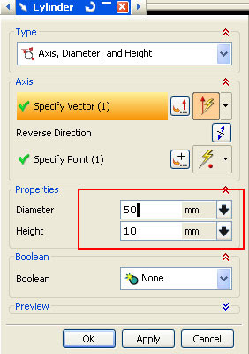
1. make a cylinder with diameter 50 and height 10, you can use icon cylinder in feature toolbar, or look how to make cylinder at this post
http://ugs-tutor.blogspot.com/2008/06/make-simple-bolt.html
then at the dialog box fill diameter with 50, and height 10 like picture below
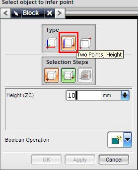
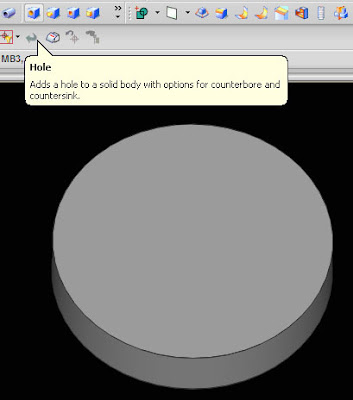
2. at the cylinder make hole with diameter 5, click the icon hole at feature toolbar.
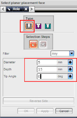
at the hole dialog box, fill the value and make sure your hole type (plain hole type- little red box at this picture)select face of cylinder using MB1 (left click)
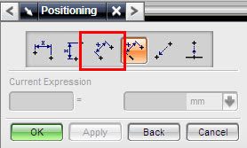
select positioning method or accept default value (it always at number 3 button from right)then click OK, or if you prefer make hole with certain value from center cylinder, choose number 4 button from right, look at picture below
then select the edge of your cylinder
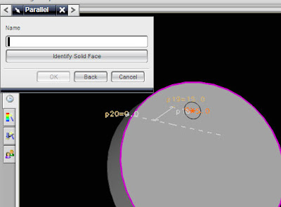
select end point button, dialog box like below will appear
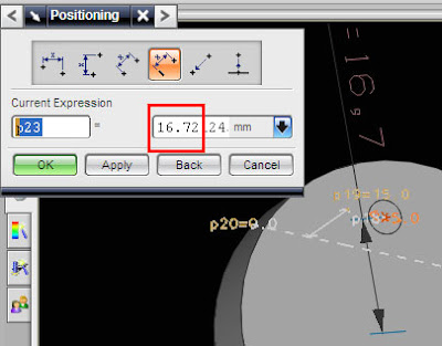
fill those box with 15, then click OK, now you have cylinder with one hole
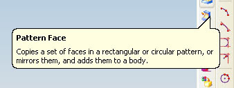
3. Make circular arrayclick the icon like picture below
after click the icon the dialog box will appear, choose circular pattern like picture below,
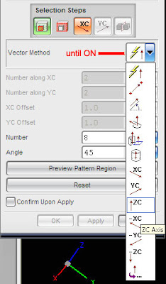
fill the number and angle like picture above. then click the face of hole in the cylinder, click MB2 (center mouse button) twice until inferred vector button on, then select Z axis arrow, finished with OK button.
or see the easy tutorial via video, your browser must installed latest adobe flash player.


 17:03
17:03