Get Unigraphics Tutorial from begining untul advance here
Please share this blog on your social network, it's make this blog keep a live and have more post,
leave some comment if you need further help

Saturday, 31 May 2008

Edge Blend Operation In UG


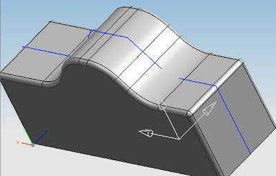
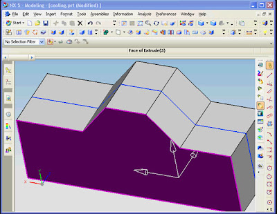
blend is operation that make edge with radius, for modeling operation it will use very often. look at picture below, we will make some edge blend operation at the edge


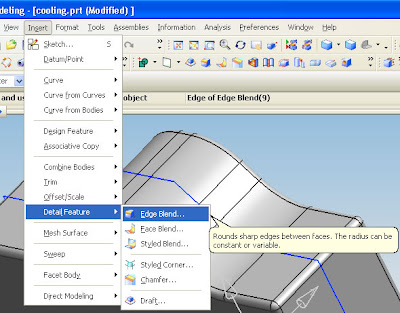
to begin blend operation click edge blend icon, for menu click insert, detail feature and choose edge blend (see piture below)


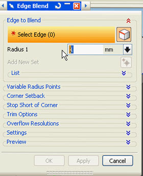
after click the edge blend icon, at the edge blend window fill the radius that you want, for example i fill with 1.


then click the edge that you want, click apply, if you finish the operation click OK, or you can continue by fill other blend radius, then click other edge.

watch the video at the top for more learning make edge blend
picture below shown the result of edge blend operation

Friday, 30 May 2008

How to export UG file to Iges format

Tutorial below is step by step instruction to export Unigraphics NX5 file format to Iges file format.

Iges file format is very useful when we works with other engineering software like C-Mold, Ansys or Abaqus
just click play video below

Saturday, 24 May 2008

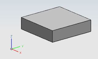
Make block solid body, using icon form feature

Actually we can make a block in various way using Unigraphic by using sketch, icon, and extrude, at this tutorial we make using icon from feature. follow step by step tutorial below
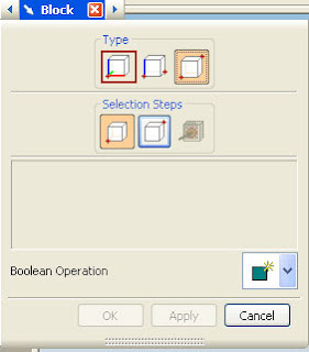
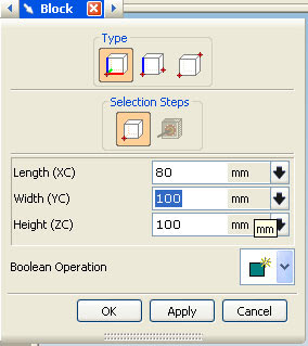
1. first choose block icon from feature.

2. dialog box will appear, there are three type method that we can chose , from left: one point, two point and diagonal point. chose one point

when you choose one point, enter the value of X,Y,Z, fill those text box with , X=80,Y=80 and Z=100.

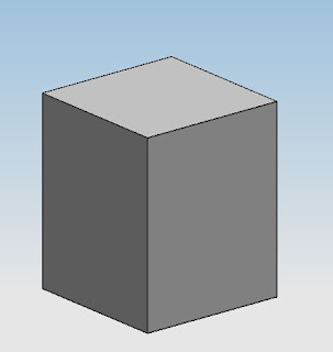
3. click oke or click MB2 in your mouse (MB2 is scroll button) or click OK button. a block will appear in your screen, (click Ctrl+F2) to fit with screen.

Congratulation you have block like picture above.
What we do when we need to change the dimension ?
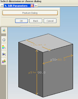
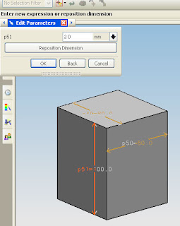
just click twice on the block, edit parameter dialog box will appear, we can edit the dimension by clicking feature dialog or by clicking the dimension that appear in the block. now let's change the z dimension from 100 to 20, click the Z dimension that appear, then change the value with 20 in dialog box, click OK, then OK again.
Step1

step2

your block dimension will change

Modeling Environment Window

Picture below shown modeling window after we make new file for modeling,


Tab menu

same with first time environment after open UGS NX5, the differences in the modeling window tab menu have more submenu. like assembly navigator, part navigator, and process studio.


part navigator use to navigate the part that we made in the modeling window, just click the plus mark to breakdown the part navigator, at the part model history we can see what we was made, and what we was do for those part, like blend, subtract, extrude, chamfer etc.

assembly navigator
it use when we assembly more than one part.

Getting Started with new file

For simple tutorial, play video tutorial below


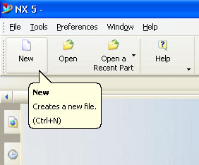
To make new file we can click icon for new file or from file chose new, or just press CTRL + N if you prefer using shortcut

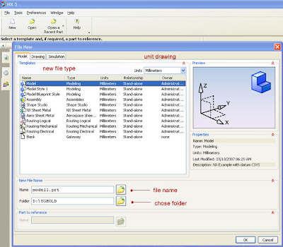
after selected new, pop up window will appear like picture below

from those pop up window you can fill file name, located folder, file type, and unit drawing.
file name & folder
just select folder icon you will guide with popup window to select your folder.to change the file name, just erased default value using delete or backspace then write your file name.
model type
or file type, at the model tab menu UGS NX5 will provide various modeling environment like, modeling, assembly, NX sheet metal, routing mechanical, routing electrical and others. not all modeling type available or should works, it's very depend with your license.
Units Drawing
basically we can chose one from three that available from UG
inch, millimeters or all.

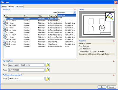
from this step we can also make drawing, just click tab drawing then you will able to choose your sheet plane size. ( see picture below)

Unigraphics NX 5 first time environment

Picture below shown first time environment after we click icon to begin work in Unigraphics NX 5


Drop Drown menu
with this menu under filw we can make new file, open file, close part and selected part, setting the utilities, open recent document and exit from UG NX5, under tools we can make update, reuse library, and other. under preferences we can change setting the environment of UGS NX5 like color, journal, macro, visualization and others.
picture below shown drop down menu of file


Tips
if you don't understand the function of submenu just hold your selection about 1.5 second. then popup explanation will come out.

Tab Menu
it contain three parts
1. IE browser, default we will open ugs.com (see picture below)

2. History
from this tabmenu we can open some file that we was made in few days ago

3.Roles
this menu used for manufacture or industrial purpose

Let's Start UG NX5

NX includes well established capabilities for 3D annotation, and Siemens’ customers worldwide are actively utilizing and endorsing 3D annotation on their solid model designs. Supporting all the major concepts and requirements defined in ASME Y14.41, this comprehensive list of capabilities in NX 5 provides the most complete collection of tools offered within a CAD product to date, and further enhancements are being developed.
NX 5 collects these capabilities under a menu selection that contains all the tools necessary for making 3D models the master repository for all product and manufacturing data.The PMI toolbar provides a single, unified interface for creating, editing and querying PMI on the solid design. In addition to facilitating the creation of 3D product definitions, this tool will check models for compliance with the ASME standard, offering the options of stringent and relaxed compliance levels.

CAD APPLICATION

With a comprehensive range of computer aided design (CAD) applications, NX is unmatched in power and flexibility when it comes to mechanical design and engineering. NX offers a broad set of CAD solutions for the design of complex mechanical products – including dedicated solutions for processes like routed system design, sheet metal design, and plastic part design – that deliver higher efficiency and shorter design cycles at lower costs. NX enables design professionals of any skill level to consider more alternatives, evaluate them more thoroughly, and get to market with innovative designs of superior quality.

NX design applications include tools for:

* Human Modeling
* Modeling
* Assembly Design
* System-based Modeling
* User-defined Features
* Routed Systems Design
* Drafting
* Sheet Metal Design
* Flexible Printed Circuit Design Fact Sheet

With NX, efficiency and cost savings extend far beyond the design process to all phases of product development. NX dynamically integrates CAD design with planning, simulation, manufacturing and other develpment processes to help ensure that design decisions can be made more quickly, with detailed knowledge of product performance and any potential manufacturability issues.
Productive

Complex products and processes demand user interactions and workflows that reduce complexity. NX streamlines decision-making by providing critical information where it is needed. Intelligent user interfaces provide dynamic feedback that accelerates design workflows, whether you are interactively creating product models or weighing performance and manufacturing cost trade-offs.

NX design is intelligent – the productive environment organizes tools, commands and information in straightforward workflows that direct the designer’s input to accomplish tasks very efficiently. On-screen displays provide instant feedback and convenient user input control without diverting attention from the task at hand. Part and assembly navigation aids enable designers to quickly comprehend the structure and techniques used to create product models. To reduce of error, NX provides previews for design commands, helping designers to proceed with confidence.
Structured

NX goes far beyond traditional CAD. Using process automation and knowledge capture tools, NX enables reusable and disciplined processes when required. This directly supports processes like lean design, design for six sigma, component and process reuse, and adherence to organizational and industry standards. NX enables companies to balance structured, repeatable best practices with the flexibility they need to move innovation forward.

NX captures design intent through intelligent user input methods, enabling intelligent design modifications and model updates. It leads the designer through an intuitive process of querying ambiguous design decisions that need to be made when changes occur.
Managed

The seamless integration of NX design with data and process management capabilities ensures a continuously up-to-date and synchronized digital product model for the entire team to use. The NX Engineering Process Management manages and protects your product data with access and security controls. It also helps manage product complexity with automated bill of materials management and synchronization, product configurations, options and variants.

Intuitive workflows in NX present tools to the designer when they are most needed, with real-time feedback.
 
Design by Free WordPress Themes | - Premium Blogger Themes |