Get Unigraphics Tutorial from begining untul advance here
Please share this blog on your social network, it's make this blog keep a live and have more post,
leave some comment if you need further help

Saturday, 12 July 2008

Rotate and Copy Object in Unigraphics

Video below is other operation of transformation in Unigraphics, if previous post we have learned to rotate some object or part, now at this video we will learn to rotate and copy the object.

to begin transform operation is same with previous post, use short cut CTRL + T, after class selection window appear select the object and so on, at the end, when move and copy button appear select copy.

look the video below to learn more

Online Videos by Veoh.com

Friday, 11 July 2008

Rotate an object by point and two axis in Unigraphics

some times we need to rotate our object or part that we draw in UGS, they are some way to rotate an object in UGS, video below will shown how to rotate using point and two axes,

the basic principle is, point that we select will become point reference (0,0,0) than two axes selected become direction, at this video sample Y and Z, axis that does not selected will become rotation axis (at this example X axis)


Online Videos by Veoh.com

step to rotate using two axis
0. begin operate with transforms click CTRL + T in your keybord
1. select object , then click OK
2. select rotate by two axes.
3. select the point.
4. select first axis, then click OK
5. select second axis, click ok
7. fill the angle that you want rotate.
8. click copy or move.

Thursday, 10 July 2008

Transform and Moving Part Operation, point to point

now let's learn basic transform operation, to begin transform click using shortcut CTRL + T, together, class selection object dialog box will appear like picture below


for example i have two object, and i want to transform the green pipe to outer side, after class selection object appear, click the green pipe that we want to move


green pipe color will change after selected, now transformation dialog box will appear like picture below


at those dialog box, choose transform , we can choose point to point or using delta length of movement, choose point to point


make sure your quadrant point icon is on position and center circle in off position


then select quadrant in drop down menu like picture below


click quadrant position at green pipe,click MB2 (center/scroll mouse), then click target the other quadrant object.
then click move to move without copy, or select copy if want copy those object to others position.

Friday, 27 June 2008

Basic block using two point and height specified

Basic tutorial to make 3D block using two point and height specified, step to make block are
1. click icon block


2. select two point and height,number two icon like picture below


3. Top view your screen
4. select two point at your screen
5. click OK

video tutorial also available below


Online Videos by Veoh.com

Thursday, 26 June 2008

Make Array hole in cylinder, Circular pattern, Unigraphics Tutorial


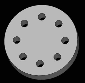
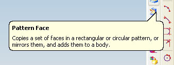
make array face in cylinder like hole, boss or other shape is easy using Unigraphics, to begin make array model, use pattern face, this icon located in direct modeling tool bar, by using this icon we can make array face, circular pattern face, rectangular array face in other.
click the icon of pattern face like picture below


if you prefer learn using video, here i capture step to make array pattern

Online Videos by Veoh.com direct

Step by Step to make circular array
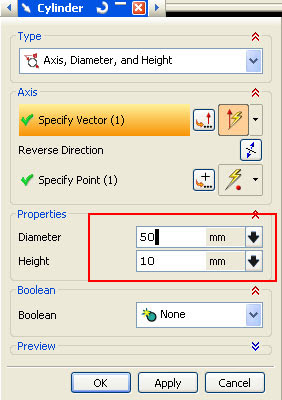
1. make a cylinder with diameter 50 and height 10, you can use icon cylinder in feature toolbar, or look how to make cylinder at this post http://ugs-tutor.blogspot.com/2008/06/make-simple-bolt.html


then at the dialog box fill diameter with 50, and height 10 like picture below
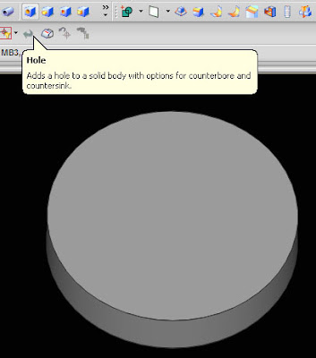
2. at the cylinder make hole with diameter 5, click the icon hole at feature toolbar.
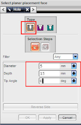
at the hole dialog box, fill the value and make sure your hole type (plain hole type- little red box at this picture)select face of cylinder using MB1 (left click)
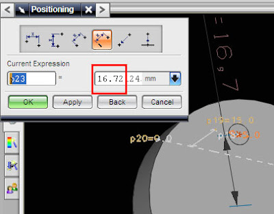
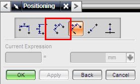
select positioning method or accept default value (it always at number 3 button from right)then click OK, or if you prefer make hole with certain value from center cylinder, choose number 4 button from right, look at picture below

then select the edge of your cylinder
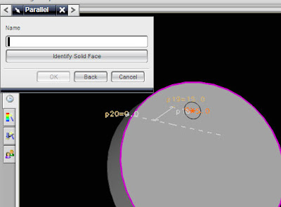


select end point button, dialog box like below will appear
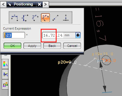

fill those box with 15, then click OK, now you have cylinder with one hole

3. Make circular array
click the icon like picture below
after click the icon the dialog box will appear, choose circular pattern like picture below,
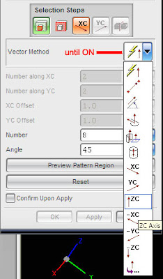

fill the number and angle like picture above. then click the face of hole in the cylinder, click MB2 (center mouse button) twice until inferred vector button on, then select Z axis arrow, finished with OK button.

or see the easy tutorial via video, your browser must installed latest adobe flash player.

Thursday, 19 June 2008

Make Shaft using Sketch and Revolve

by using revolve we can make simple and complex 3D model from 2D model that have cylinder shape, like shaft, bolt, drum, pulley, fly wheel and other cylinder product.
now our project at this post is make shaft like picture below


Step to make shaft are
1. open sketch
2. make a half 2D shaft using profile
3. finish sketch , revolve the half 2D sketch model.

to begin using revolve, click in the feature toolbar, like picture below


to learn step by step of this tutorial, please refer to video below to learn make shaft using revolve feature, here i try to upload in veoh, because i think veoh video quality is better than youtube, although same times any advertisement added in video


Online Videos by Veoh.com

Wednesday, 18 June 2008

Begining Sketch Operation, Extrude

last month i post how to make block easier using Form Feature Operation, now let's learn make more attractive block using sketch in unigraphics NX5, sketch is basic feature in UGS that we can make block, cylinder, pipe and other 3D model from 2D model. so let's try make 3D model from 2D model.
Begin Sketch using Icon
to begin sketch click the sketch icon like picture below, it usually located at feature tool bar.


to see how to use sketch, to make block, try to play this video


after clicking the icon, next step is define the plane of sketch, default plane are X -Y plane, if we clicking OK to the default value, we will make sketch plane on X - Y Plane. as see on picture below, we can choose sketch plane. direction of plane, plane option and reference. at this tutorial we use X-Y default plane.


after click OK, Sketch plane will available, at those plane we can drawing using 2D model type like line, arc, profile, circle. try using profile to make like continues line connection.

we can choose preferred snap point option, when we choose profile we also can choose basic shape, line or arc.

begin to sketch with 0,0 coordinate, click the 0,0 then bring it horizontal click other position and the closed line connection like picture below.


then after make closed connection line, right click your mouse choose OK.


EXTRUDE OPERATION

we can make 3D model using extrude operation from 2D model like sketch or line, to begin extrude operation click the extrude icon


dialog box will appear, fill the end distance value 25, then click to 2D sketch line, click OK.


3D model from extrude and sketch will appear like picture below

 
Design by Free WordPress Themes | - Premium Blogger Themes |